
 +8613126993997



Industry News



0102030405
Applications and Circuit Examples of Relief Valves in Hydraulic Systems
2026-09-18
I am Victor. I own a 6,000 m² factory in China and am a renowned relief valve expert.
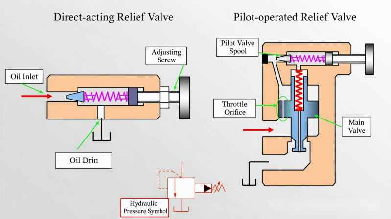
A relief valve is an inlet pressure control valve. When inlet pressure reaches the set value, the valve port opens to overflow.
relief valves are crucial in hydraulic systems, especially in fixed-displacement pump systems—without a relief valve, the system can hardly function.
Pressure Regulation and Stabilization
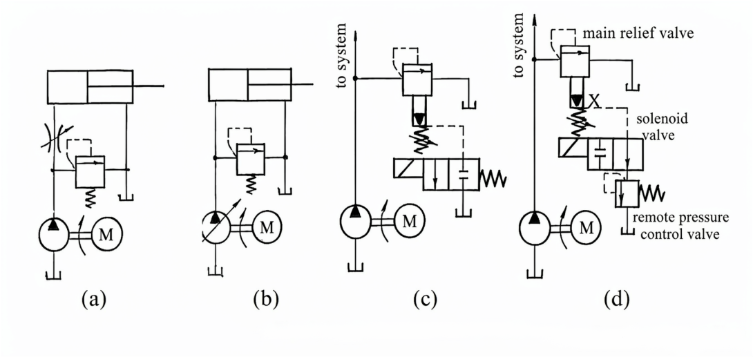
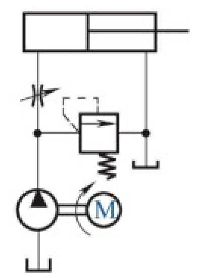
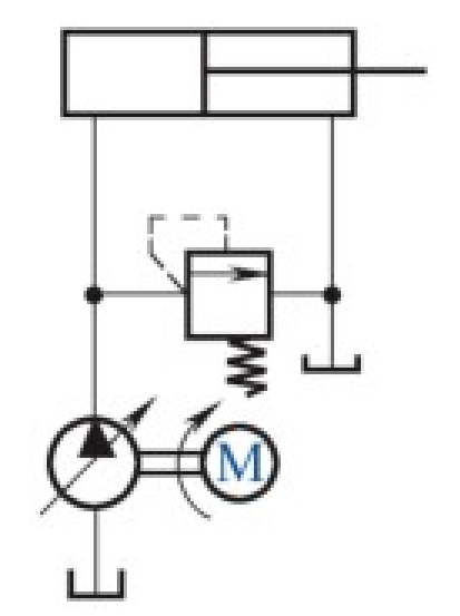
The system uses a fixed-displacement pump for oil supply, with a Throttle Valve or flow control valve installed on the inlet or return line. This allows part of the pressure oil output by the pump to enter the cylinder for work, while excess oil must flow back to the tank through the relief valve. The relief valve remains in a normally open state at its set pressure.
Adjusting the spring compression adjusts the system's working pressure. The pump's working pressure is determined by the relief valve's setting and remains constant. In this case, the relief valve functions as a pressure-regulating and stabilizing device.
Safety Protection (Safety Valve)
The system uses a variable-displacement pump for oil supply. The pump output automatically adjusts to demand with load changes, so there is no excess oil needing overflow, and working pressure is determined by the load.
The relief valve is placed at the pump outlet and only opens during overload, providing safety protection for the system. Thus, the relief valve in this system is also called a safety valve, and it remains normally closed during normal system operation.
To maintain normal system operation, the safety valve setting pressure should be 10%–20% higher than the system's maximum working pressure.
Used as a Pump Unloading Valve
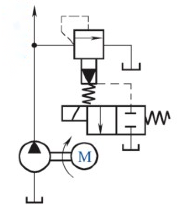
When the solenoid is energized, the remote control port of a pilot-operated relief valve connects to the tank, effectively setting the Pilot Valve adjustment to zero. At this point, the main spool lifts rapidly even at very low inlet pressure, unloading the pump to reduce energy loss and pump wear.
Remote Pressure Control
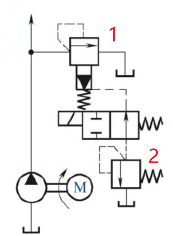
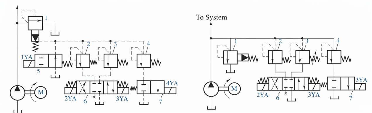
Connect the external control port of relief valve 1 to the inlet of a conveniently located remote pressure control valve (relief valve 2). When the solenoid of the directional valve is de-energized, its right position is active, connecting the external control port of pilot-operated relief valve 1 to the low-pressure regulating valve 2. When the oil pressure in the upper chamber of main spool 1 reaches the setting pressure of the low-pressure valve 2, the main spool lifts to overflow (its pilot valve no longer performs pressure regulation), thus achieving remote pressure control.
Backpressure Generation
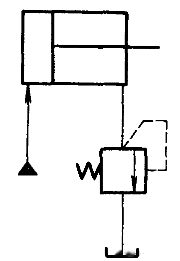
Installing a relief valve on the return line of a hydraulic cylinder means the return chamber can only connect to the tank when pressure reaches the valve setting, creating backpressure in the cylinder return chamber. This prevents the piston from surging forward when the load suddenly decreases, improving the smoothness of moving components.
In this case, the relief valve setting is low, and a direct-acting low-pressure relief valve is generally used.
Multi-Stage Pressure Control
Connecting the external control port of a relief valve to several remote pressure control valves via a directional valve enables high-low multi-stage pressure control.
Each valve should have the same rated flow as the pump, making them relatively large in size. Therefore, this arrangement is only suitable for systems with small flow rates.
Contact me via WhatsApp: +86 15356071276