
 +8613126993997



Industry News




0102030405
Relief Valve Technical Analysis
2026-09-09
I am Victor. I own a 6,000 m² factory in China and am a renowned relief valve expert.
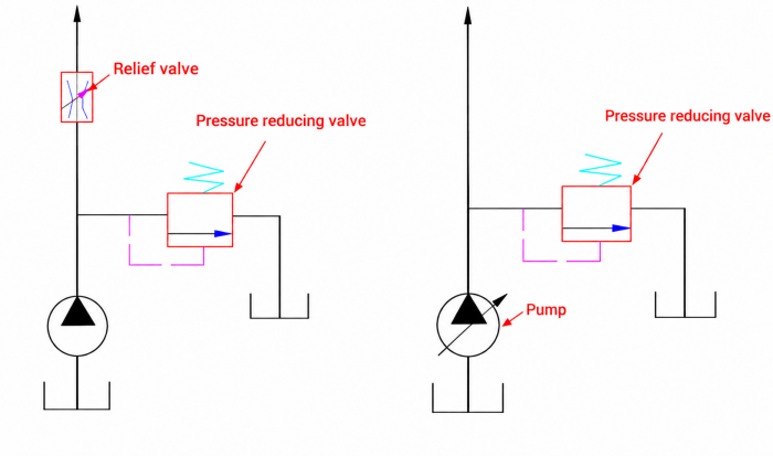
A friend left a comment asking about relief valves, so in this post, let's break them down together and understand the differences in working principles between relief valves and reducing valves.
- Working Principle of relief valves
- Main Functions of relief valves
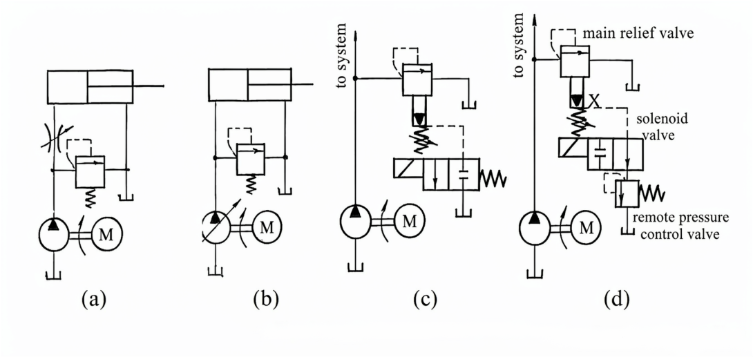
First, in a fixed-displacement pump throttling system, it is used to maintain constant pump outlet pressure and divert excess medium from the pump outlet back to the tank—in this case, the relief valve acts as a pressure-maintaining and overflow device. Second, it serves a safety function in the system.
- Direct-Acting and Pilot-Operated Types
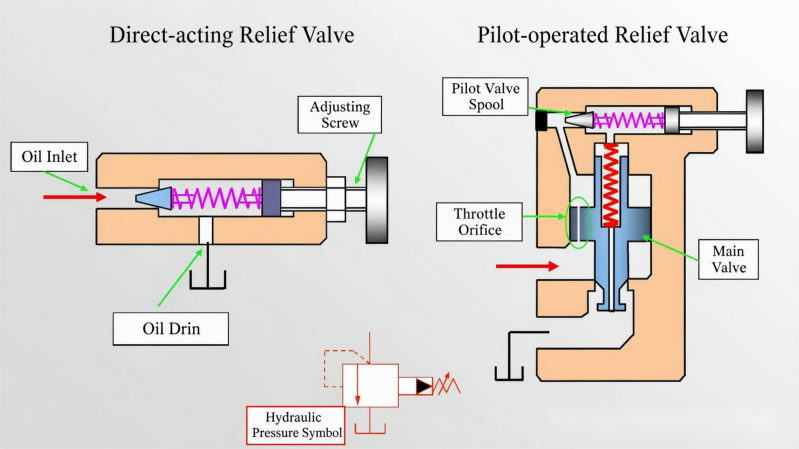
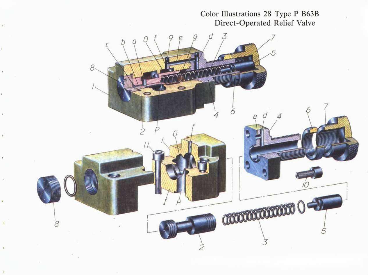
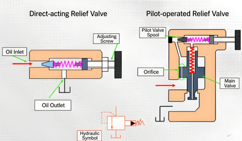
Based on structural differences, relief valves can be classified into direct-acting and pilot-operated types. Main components include the valve body, valve spool, spring, and other accessories. When pressure reaches the relief valve setting (determined by spring stiffness), the valve port opens and oil overflows. A direct-acting relief valve uses the spring force at the top of the spool to directly balance against the hydraulic pressure on the bottom face to control the relief pressure. Generally, direct-acting valves are only made as low-pressure, small-flow relief valves.
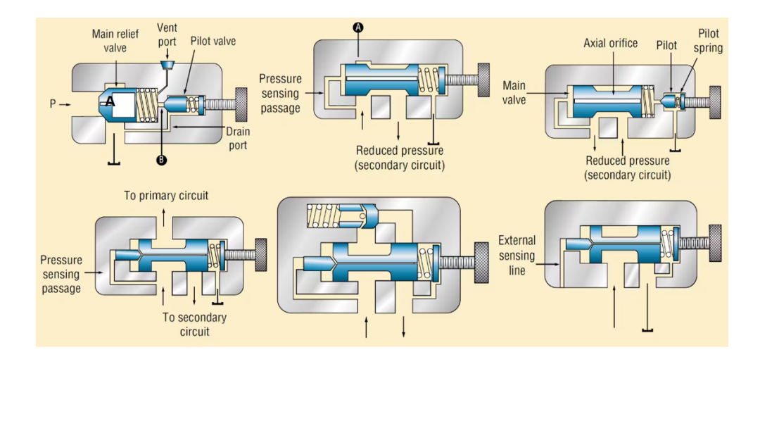
When a pilot-operated relief valve operates, the pilot valve and main valve spool are each in a state of force balance. The pressure value is mainly determined by the pre-compression of the pilot valve's adjusting spring, while the main valve spring serves a reset function. The flow through the pilot valve is very small—about 1% of the main valve's rated flow—so its size is very compact. Even for high-pressure valves, the spring stiffness remains relatively low. This greatly improves the valve's adjustment performance.
- Video Content Review
Stage 1: The relief valve preset pressure is 800 psi, while system pressure is also 800 psi. 100% of pump flow returns to the tank through the relief valve.
Stage 2: The relief valve preset pressure is increased to 1,000 psi, and system pressure begins to rise. When system pressure reaches 500 psi, 5% of flow passes through the relief valve. When system pressure reaches 750 psi, 50% of flow passes through the relief valve.
Stage 3: When system pressure reaches 1,000 psi, the relief valve is fully open.
- Detailed Comparison of Working Principles: Relief Valve vs. Reducing Valve
- Core Function Differences
| Dimension | Relief Valve | Reducing Valve |
| Core Function | Limits maximum system pressure (safety protection) | Stabilizes outlet pressure of branch circuit (pressure reduction regulation) |
| Action Target | Constant inlet pressure (opens to relieve flow when overpressure) | Constant outlet pressure (closes/throttles when overpressure) |
| System Role | Safety valve / pressure stabilizer | Branch pressure regulator |
- Structural and Operating Characteristics
| Feature | Relief Valve | Reducing Valve |
| Normal Valve State | Normally closed (closed under normal pressure) | Normally open (remains connected under normal pressure) |
| Connection Method | Connected in parallel at main circuit outlet (outlet leads directly to tank) | Connected in series in branch circuit requiring pressure reduction (outlet connects to actuator) |
| Drain Method | Internal drain (spring chamber oil returns to outlet) | External drain (spring chamber requires separate return line to tank) |
| Control Signal Source | Inlet pressure feedback | Outlet pressure feedback |
- Dynamic Process Examples
- Relief valve: System pressure ↑ → spool is pushed open, overflow occurs → inlet pressure stabilizes.
- Reducing valve: Outlet pressure ↑ → spool closes/throttles the orifice → outlet pressure stabilizes.
Contact me via WhatsApp: +86 15356071276